- 您现在的位置:买卖IC网 > Sheet目录1243 > SI5020-EVB (Silicon Laboratories Inc)BOARD EVALUATION FOR SI5020
�� �
�
�Si5020-EVB�
�Functional� Description�
�The� evaluation� board� simplifies� characterization� of� the�
�Si5020� Clock� and� Data� Recovery� (CDR)� device� by�
�providing� access� to� all� of� the� Si5020� I/Os.� Device�
�performance� can� be� evaluated� by� following� the� Test�
�Configuration� section� below.� Specific� performance�
�metrics� include� jitter� tolerance,� jitter� generation,� and�
�jitter� transfer.�
�Power� Supply�
�The� evaluation� board� requires� one� 2.5� V� supply.� Supply�
�filtering� is� placed� on� the� board� to� filter� typical� system�
�noise� components,� however,� initial� performance� testing�
�should� use� a� linear� supply� capable� of� supplying� 2.5� V�
�±5%� dc.�
�CAUTION� :� The� evaluation� board� is� designed� so� that� the�
�body� of� the� SMA� jacks� and� GND� are� shorted.� Care� must�
�be� taken� when� powering� the� PCB� at� potentials� other�
�than� GND� at� 0.0� V� and� VDD� at� 2.5� V� relative� to� chassis�
�GND.�
�Self-Calibration�
�The� Si5020� device� provides� an� internal� self-calibration�
�To� improve� the� DATAOUT� eye-diagram,� short� 100� ?�
�transmission� line� segments� precede� the� 50� ?� high-�
�speed� traces.� These� segments� increase� the� interface�
�bandwidth� from� the� chip� to� the� 50� ?� traces� and� reduce�
�data� inter-symbol-interference.� Please� refer� to� Silicon�
�Laboratories� application� note� AN43� for� more� details.�
�Note:� The� 50� ?� termination� is� for� each� terminal/side� of� a� dif-�
�ferential� signal,� thus� the� differential� termination� is� actu-�
�ally� 50� ?� +� 50� ?� =� 100� ?� .�
�REFCLK�
�REFCLK� is� used� to� center� the� frequency� of� the�
�DSPLL?� so� that� the� device� can� lock� to� the� data.� Ideally�
�the� REFCLK� frequency� should� be� 1/128th,� 1/32nd,� or�
�1/16th� the� VCO� frequency� and� must� have� a� frequency�
�accuracy� of� ±100� PPM.� Internally,� the� CDR�
�automatically� recognizes� the� REFCLK� frequency� within�
�one� of� these� three� frequency� ranges.� Typical� REFCLK�
�frequencies� are� given� in� Table� 1.� REFCLK� is� AC�
�coupled� to� the� SMA� jacks� located� on� the� top� side� of� the�
�evaluation� board.�
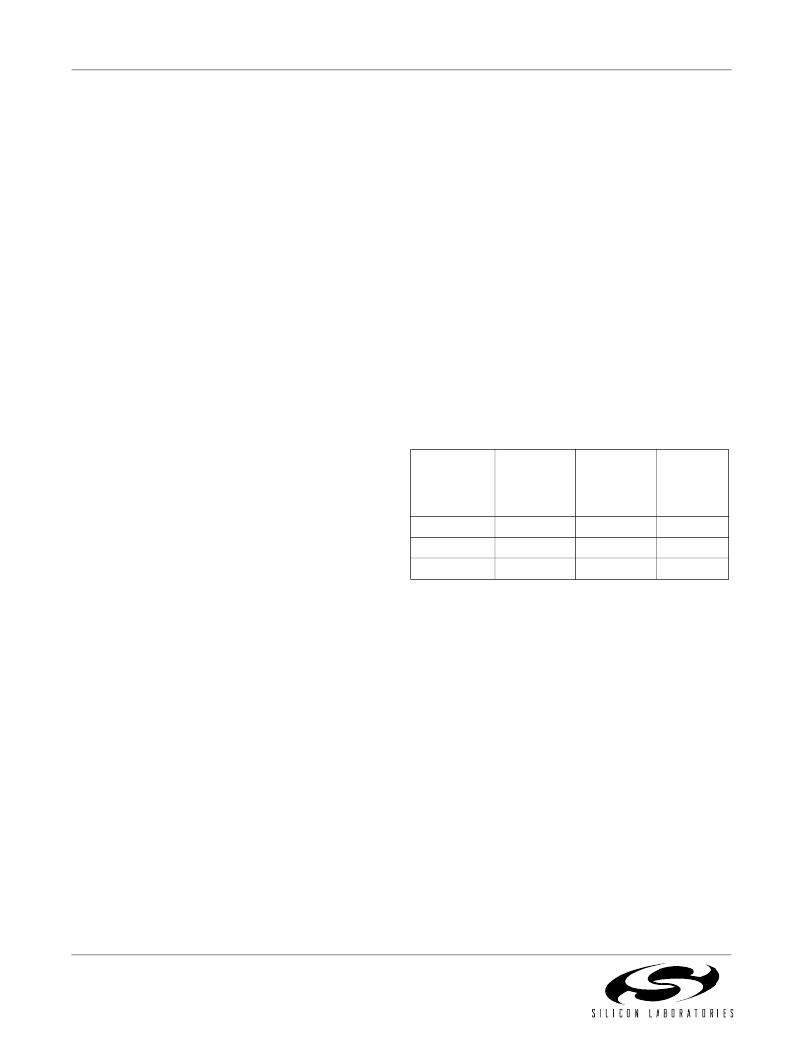
�Table� 1.� Typical� REFCLK� Frequencies�
�function� that� optimizes� the� loop� gain� parameters� within�
�the� internal� DSPLL� TM� .� Self-calibration� is� initiated� by� a�
�high-to-low� transition� of� the� PWRDN/CAL� signal� while� a�
�valid� reference� clock� is� supplied� to� the� REFCLK� input.�
�On� the� Si5020-EVB� board,� a� voltage� detector� IC� is�
�utilized� to� initiate� self-calibration.� The� voltage� detector�
�drives� the� PWRDN/CAL� signal� low� after� the� supply�
�voltage� has� reached� a� specific� voltage� level.� This� circuit�
�is� described� in� Silicon� Laboratories� application� note�
�SONET/SDH�
�19.44� MHz�
�77.76� MHz�
�155.52� MHz�
�Gigabit�
�Ethernet�
�19.53� MHz�
�78.125� MHz�
�156.25� MHz�
�SONET/�
�SDH� with�
�15/14� FEC�
�20.83� MHz�
�83.31� MHz�
�166.63� MHz�
�Ratio� of�
�VCO� to�
�REFCLK�
�128�
�32�
�16�
�AN42.� On� the� Si5020-EVB,� the� PWRDN/CAL� signal� is�
�also� accessible� via� a� jumper� located� in� the� lower� left-�
�hand� corner� of� the� evaluation� board.� PWRDN/CAL� is�
�wired� to� the� signal� post� adjacent� to� the� 2.5� V� post.�
�Device� Powerdown�
�The� CDR� can� be� powered� down� via� the� PWRDN/CAL�
�signal.� When� asserted� the� evaluation� board� will� draw�
�minimal� current.� PWRDN/CAL� is� controlled� via� one�
�jumper� located� in� the� lower� left-hand� corner� of� the�
�evaluation� board.� PWRDN/CAL� is� wired� to� the� signal�
�post� adjacent� to� the� 2.5� V� post.�
�CLKOUT,� DATAOUT,� DATAIN�
�These� high-speed� I/Os� are� wired� to� the� board� perimeter�
�on� 30� mil� (0.030� inch)� 50� ?� microstrip� lines� to� the� end-�
�launch� SMA� jacks� as� labeled� on� the� PCB.� These� I/Os�
�are� AC� coupled� to� simplify� direct� connection� to� a� wide�
�array� of� standard� test� hardware.� Because� each� of� these�
�signals� are� differential� both� the� positive� (+)� and� negative�
�(–)� terminals� must� be� terminated� to� 50� ?� .� Terminating�
�only� one� side� will� adversely� degrade� the� performance� of�
�the� CDR.� The� inputs� are� terminated� on� the� die� with� 50� ?�
�resistors.�
�RATESEL�
�RATESEL� is� used� to� configure� the� CDR� to� recover� clock�
�and� data� at� different� data� rates.� RATESEL� is� a� two� bit�
�binary� input� that� is� controlled� via� two� jumpers� located� in�
�the� lower� left-hand� corner� of� the� evaluation� board.�
�RATESEL0/1� are� wired� to� the� center� posts� (signal� post)�
�between� 2.5� V� and� GND.� For� example,� the� OC-48� data�
�rate� is� selected� by� jumping� RATESEL0� to� 0.0� V� and�
�RATESEL1� to� 0.0� V.�
�The� table� given� on� the� evaluation� board� lists�
�approximate� data� rates� for� the� jumper� configurations�
�shown� in� Figure� 1.� Applications� with� data� rates� within�
�±7%� of� the� given� data� rate� are� also� accommodated.�
�2�
�Rev.� 1.0�
�发布紧急采购,3分钟左右您将得到回复。
相关PDF资料
SI5023-EVB
BOARD EVALUATION FOR SI5023
SI5110-EVB
BOARD EVALUATION FOR SI5110
SI5320-EVB
BOARD EVALUATION FOR SI5320
SI5321-EVB
BOARD EVALUATION FOR SI5321
SI5364-EVB
BOARD EVALUATION FOR SI5364
SI5XX-PROG-EVB
KIT EVALUATION FOR SI5XX
SI84XXCOM-RD
KIT EVAL FOR SI84XXCOM
SILICON-EXPLORER II
SOFTWARE ANALYSIS EXPLORER LOGIC
相关代理商/技术参数
SI-50210-F
功能描述:CONN MAGJACK 1PT 10/100BTX G/Y RoHS:是 类别:连接器,互连式 >> 模块 - 带磁性元件的插座 系列:MagJack® ST SI-50000 标准包装:63 系列:Mag45 连接器类型:RJ45 端口数:1 行数:1 安装类型:面板安装,通孔,直角 速度:10/100 Base-T 板上方高度:0.555"(14.10mm) LED 颜色:绿 - 绿 每一插座芯体的数目:5 屏蔽:屏蔽 翼片方向:上 特点:板锁 包装:托盘
SI-50211-F
功能描述:CONN MAGJACK 1PT 10/100BTX G/G RoHS:是 类别:连接器,互连式 >> 模块 - 带磁性元件的插座 系列:MagJack® ST SI-50000 标准包装:63 系列:Mag45 连接器类型:RJ45 端口数:1 行数:1 安装类型:面板安装,通孔,直角 速度:10/100 Base-T 板上方高度:0.555"(14.10mm) LED 颜色:绿 - 绿 每一插座芯体的数目:5 屏蔽:屏蔽 翼片方向:上 特点:板锁 包装:托盘
SI-50212-F
功能描述:CONN MAGJACK 1PT 10/100BTX Y/G RoHS:是 类别:连接器,互连式 >> 模块 - 带磁性元件的插座 系列:MagJack® ST SI-50000 标准包装:63 系列:Mag45 连接器类型:RJ45 端口数:1 行数:1 安装类型:面板安装,通孔,直角 速度:10/100 Base-T 板上方高度:0.555"(14.10mm) LED 颜色:绿 - 绿 每一插座芯体的数目:5 屏蔽:屏蔽 翼片方向:上 特点:板锁 包装:托盘
SI-50213
制造商:BEL 制造商全称:Bel Fuse Inc. 功能描述:SI-50213
SI-50214-F
功能描述:CONN MAGJACK 1PT 10/100BTX GO/Y RoHS:是 类别:连接器,互连式 >> 模块 - 带磁性元件的插座 系列:MagJack® ST SI-50000 标准包装:63 系列:Mag45 连接器类型:RJ45 端口数:1 行数:1 安装类型:面板安装,通孔,直角 速度:10/100 Base-T 板上方高度:0.555"(14.10mm) LED 颜色:绿 - 绿 每一插座芯体的数目:5 屏蔽:屏蔽 翼片方向:上 特点:板锁 包装:托盘
SI-50215
制造商:BEL 制造商全称:Bel Fuse Inc. 功能描述:SI-50215
SI-50215-F
制造商:BEL 制造商全称:Bel Fuse Inc. 功能描述:SI-50215-F
SI-50216-F
制造商:BEL 制造商全称:Bel Fuse Inc. 功能描述:SI-50216-F